The diverse collection of capacitor types has not changed much over recent years, but applications certainly have. In this article, we look at how capacitors are used in power electronics and compare the available tech- nologies. Film capacitors are showing their advantages in upcoming applications such as electric vehicles, alter- native energy power conversion, and inverters in drives. However, aluminum (Al) electrolytics are still important when energy storage density is the main requirement.
Al Electrolitic or Film Capacitor ?
It is easy to dismiss Al electrolytics as yesterday’s technology, but the differentiation in performance between them and the film alternative is not always so clear. In terms of stored energy density, i.e., joules/cubic centimeters, they are still ahead of standard film capacitors, although exotic variants such as segmented high-crystalline metalized polypropylene are comparable. Also, Al electrolytics maintain their ripple-current rating at higher temperatures better than competing film capacitors. Even the perceived life and reliability issues are not so significant when Al electrolytics are appropriately derated. Al electrolytics are still very attractive where the ride-through of a dc bus voltage on a power outage is required without battery back-up. For example, when cost is a driving factor, it is especially difficult to anticipate film capacitors taking over from the bulk capacitors in commodity off-line power supplies.
Film Wins in Many Ways
Film capacitors have several significant advantages over other capacitors: equivalent series resistance (ESR) ratings can be dramatically lower, leading to much better ripplecurrent handling. Surge-voltage ratings are also superior, and, perhaps most significantly, film capacitors can self-heal

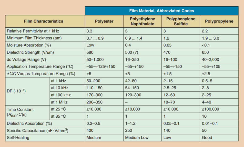
FIG 1 The capacitor film characteristics.

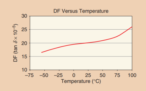
FIG 2 The variation of the DF with the temperature for polypropylene film.
After stress, leading to better system reliability and lifetime. However, the ability to self-heal depends on the stress level, peak values, and repetition rate. Additionally, eventual catastrophic failure is still possible due to carbon deposition and collateral damage from the plasma arc generated during fault clearing. These characteristics match the modern applications of power conversion in electric vehicles and alternative energy systems where there is no hold up required with outages or between line-frequency ripple peaks. The main requirement is the ability to source and sink high-frequency ripple currents that might reach hundreds if not thousands of amps while maintaining tolerable losses and high reliability. There is also a movement to higher bus voltages to reduce ohmic losses at given power levels. This would mean a series connection of Al electrolytics with their inherent maximum voltage rating of approximately 550 V. To avoid a voltage imbalance, it may be necessary to choose the expensive capacitors with matched values and use voltage balancing resistors with their associated losses and cost.
The reliability issue is not straightforward, although, under controlled conditions, electrolytics are comparable with power film, meaning that they will typically withstand only 20% of overvoltage before damage occurs. In contrast, film capacitors can withstand perhaps 100% of overvoltage for limited periods. Upon failure, electrolytics can short-circuit and explode, taking down a whole bank of series/parallel components with a dangerous electrolyte discharge. Film capacitors can also self-heal, but system reliability under authentic conditions of occasional stress can be very different between the two types. As with all components, high humidity levels can degrade film capacitor performance, and, for best reliability, this should be well controlled. Another practical differentiator is the ease of mounting film capacitors—they are available in insulated, volumetrically efficient rectangular box enclosures with a variety of electrical connection options, from screw terminals to lugs, fastons, and bus bars, compared with the typical round metal cans of electrolytics. The nonpolar dielectric film gives reverse-proof mounting and allows use in applications where ac is applied, such as in inverter-output filtering.
Of course, there are many film capacitor dielectric types available, and Figure 1 gives a summary of their comparative performances [1]. Polypropylene film is the overall winner when losses and reliability under stress are the main considerations because of its low DF and high dielectric breakdown per unit thickness. The other films can be better for temperature rating and capacitance/volume, with higher dielectric constants and thinner film availability, and, at low voltages, polyester is still in common use. The DF is particularly important and defined as ESR/capacitive reactance, and it is usually specified at 1 kHz and 25 °C. A low DF in comparison to other dielectrics implies lower heating and is a way of comparing losses per microfarad. DF slightly varies with frequency and temperature, but polypropylene performs best. Figures 2 and 3 show the typical plots.
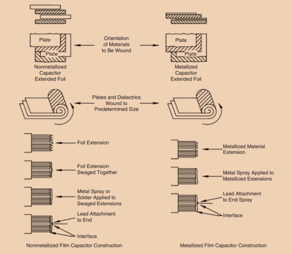
There are two main types of film capacitor constructions that use foil and deposited metallization, as shown in Figure 4. Metal foil that is approximately 5-nm thick is typically used between dielectric layers for its high peak-current capability, but it does not self-heal after enduring stress. Metalized film is formed by a vacuum and by typically depositing Al at 1,200 °C onto the film to a thickness of roughly 20–50 nm with the film’s temperature ranging from −25 to −35 °C,

FIG 3 The variation of the DF with the frequency for polypropylene film.

FIG 4 The film capacitor construction
although zinc (Zn) and Al-Zn alloys can also be used. This process enables self-healing, where breakdowns at any point throughout the dielectric cause localized intense heating, perhaps up to 6,000 °C, causing a plasma to form. The metallization around the breakdown channel is vaporized, with the rapid expansion of the plasma quenching the discharge, which isolates the defect and leaves the capacitor fully functional. The reduction of capacitance is minimal but additive over time, making it a useful indicator of the aging of the component.
A common method for further reliability enhancement is to segment the metallization on the film into areas, perhaps millions, with narrow gates feeding the current into the segments and acting as fuses for gross overloads. The narrowing of the total current path to the metallization does reduce the peak current handling of the component, but the extra safety margin introduced allows the capacitor to be usefully rated at higher voltages.
Modern polypropylene has a dielectric strength of approximately 650 V/µm and is available in thicknesses of roughly 1.9 µm and upward, so capacitor voltage ratings up to several kilovolts are routinely attainable, with some parts even rated at 100 kV. However, at higher voltages, the phenomenon of partial discharge (PD), also known as corona discharge, becomes a factor. PD is the high-voltage breakdown of microvoids in the bulk of material or in the air gaps between layers of material, causing a partial short circuit of the total insulating path. PD (corona discharge) leaves a slight carbon trace; the initial effect is unnoticeable but can accumulate over time until a gross and sudden breakdown of the weakened, carbon-traced insulation occurs. The effect is described by the Paschen curve, shown in Figure 5, and has a characteristic inception and extinction voltage. The figure shows two example field strengths. Points above the Paschen curve, A, are likely to produce a PD breakdown.

FIG 5 The Paschen curve and example electric field strengths.
To counter the effect, very high voltage-rated capacitors are oil impregnated to exclude air from layer interfaces. Lower-voltage types tend to be resin filled, which also helps with mechanical robustness. Another solution is to form series capacitors in single housings, effectively reducing the voltage drop across each to well below the inception voltage. PD is an effect due to electric field intensity, so increasing dielectric thickness to decrease the voltage gradient is always possible but increases the overall size of the capacitor. There are capacitor designs that combine foils and metallization to provide a compromise between peak current capability and self-healing. The metallization can also be graded from the edge of the capacitor so that thicker material at the edges gives better current handling and more robust termination by soldering or welding, and the grading can be continuous or stepped.
It is, perhaps, useful to take a step back and observe how using Al-electrolytic capacitors is advantageous. One example is in a 90%-efficient, 1-kW off-line converter with a power-factor-corrected front end, needing a 20-ms ride through, as shown in Figure 6. It will typically have an internal dc bus with nominal voltage, Vn, of 400 V and a drop-out voltage, Vd, of 300 V, below which output regulation is lost.
The bulk capacitor C1 supplies energy to maintain constant output power during the specified ride-through time as the bus voltage drops from 400 to 300 V after an outage. Mathematically, Po t/h =1/2 C(Vn²-Vd²) or C=2*1000*0.02/0.9*(400²-300²) =634nF at 450 V rating.
If Al-electrolytic capacitors are used, then the equation results in a required volume of roughly 52 cm3 (i.e., 3 in 3 ), e.g., if the TDK-EPCOS B43508 series is used. In contrast, film capacitors would be impractically large, requiring perhaps 15 in parallel at a total volume of 1,500 cm3 (i.e., 91 in 3 ) if the TDK-EPCOS B32678 series is used. The difference is obvious, but the choice would change if the capacitor needed to control the ripple voltage on a dc line. Take a similar example where the 400-V bus voltage is from a battery, so the hold up is not required. However, there is a need to reduce the ripple effect to, e.g., 4 V root mean squared (rms) from 80 A rms high-frequency current pulses taken by a downstream converter at 20 kHz. This could be an electric vehicle application, and the capacitance required can be approximated from C=irms/Vrippe.2.Π.f=80/4*2*3.14*20*1000=160 uF at 450 V rating.

FIG 6 The capacitor for a ride through (hold up). HVDC: high-voltage dc.
An electrolytic at 180 µF, 450 V might have a ripplecurrent rating of only roughly 3.5 A rms at 60 °C, including frequency correction (EPCOS B43508 series). Thus, for 80 A, 23 capacitors would be required in parallel, producing an unnecessary 4,140 µF with a total volume of 1,200 cm3 (i.e., 73 in 3 ). This complies with the sometimes-quoted 20 mA/µF ripple-current rating for electrolytics. If film capacitors are considered, now, just four in parallel from the EPCOS B32678 series give a 132-A rms ripple-current rating in a volume of 402 cm3 (i.e., 24.5 in 3 ). If the temperature is restricted to, e.g., less than 70 °C ambient, then a smaller case size can still be chosen. Even if we choose electrolytics on other grounds, the excess capacitance could cause other problems, such as controlling the energy in inrush current. Of course, if transient overvoltages could occur, then the film capacitors would be far more robust in the application. An example of this would be in light traction, where an intermittent connection to a catenary causes overvoltage on the dc-link connection.
This example is typical of many environments today, such as in uninterruptible power supply systems, wind and solar power, welding, and grid-tied inverters. The cost differences between film and Al electrolytics can be summarized in figures published in 2013 [2]. The typical costs for a dc-bus from rectified 440 Vac can be found in Table 1.
Other applications are for decoupling and snubber circuits in converters or inverters. Here, film/foil construction should be used if size permits, as metalized types require special design and manufacturing steps. As decoupling, the capacitor is placed across the dc bus to provide a low inductance path for circulating high-frequency currents, typically 1 µF per 100 A switched. Without the capacitor, the current circulates through higher-inductance loops, causing transient voltages (Vtr) according to the following: Vtr =-Ldi/dt.
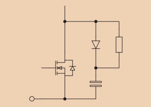
With current changes of 1,000 A/µs being possible, just a few nanohenries of inductance can produce significant voltages. Printed-circuit-board traces can have an inductance of around 1 nH/mm, providing, therefore, roughly 1 Vtr/mm in this situation. Thus, it is important for connections to be as short as possible. To control dV/dt across switches, the capacitor and a resistor/ diode network are placed in parallel with an IGBT or MOSFET (Figure 7).
This slows ringing, controls electromagnetic interference (EMI), and prevents spurious switching due to high


FIG 7 The switch snubbing. FIG 8 The film capacitors as EMI suppression. FIG 9 The film capacitors in motor-drive EMC filtering.
dV/dt, particularly in IGBTs. A starting point is often making the snubber capacitance roughly twice the sum of the switch output capacitance and mounting capacitance, and the resistor is then chosen to critically damp any ringing. More optimum design approaches have been formulated.
Safety-rated polypropylene capacitors are often used across power lines to reduce differential mode EMI (Figure 8). Their ability to withstand transient overvoltages and self-heal is crucial. Capacitors in these positions are rated as X1 or X2, which can withstand 4- and 2.5-kV transients, respectively. The values used are often in the microfarads to achieve compliance with typical electromagnetic compatibility (EMC) standards at high power levels. Film Y-type capacitors can also be used in line-to-earth positions to attenuate common mode noise where the ca pacitance value is limited due to leakage current considerations (Figure 8). Y1 and Y2 versions are available for 8- and 5-kV transient ratings, respectively. Low connection inductances of film capacitors also help keep self-resonances high.
An increasing application for nonpolarized capacitors is to form low-pass filters with series inductors to attenuate highfrequency harmonics in the ac output of drives and inverters (Figure 9). Polypropylene capacitors are often used for their reliability, high ripple-current rating, and good volumetric efficiency in the application, and the inductors and capacitors are often packaged together in one module. Loads such as motors are often distant from the drive unit, and filters are used to enable systems to meet the EMC requirements and reduce stress on cabling and motors from excessive dV/dt levels.


